Visual Guide: Heat Pump Schematic Diagram and Its Components
In Summary
A heat pump schematic diagram is a visual representation of the components and flow of a heat pump system. It shows how heat is transferred from a heat source to a heat sink using a refrigerant cycle, allowing the pump to provide heating or cooling in a controlled manner.
Understanding Heat Pumps
Heat pumps are innovative devices that play a critical role in maintaining comfortable temperatures in homes and buildings. They do this by transferring heat energy from one place to another. Understanding the basic principles of how heat pumps work and the significance of a heat pump schematic diagram can empower homeowners to comprehend their heating systems better.
Basic Principle of Heat Pumps
At the heart of every heat pump is the principle of heat transfer. Heat pumps work by moving heat from a cooler area to a warmer area, using a small amount of energy. This is contrary to the natural flow of heat, which moves from areas of high temperature to areas of low temperature.
During the heating season, heat pumps draw heat from the outdoor air or ground and move it indoors to warm the space. In contrast, during the cooling season, heat pumps extract heat from indoor air and expel it outdoors, thereby cooling the interior.
An essential part of understanding how heat pumps work involves familiarizing oneself with the various components of a heat pump and their functions. This is where a heat pump schematic diagram comes in handy.
Importance of a Schematic Diagram
A heat pump schematic diagram is a visual representation of the heat pump system. It shows how the different components of the heat pump are connected and interact with each other to perform their function.
This diagram is crucial because it allows homeowners and service professionals to understand the inner workings of a heat pump, identify each component, and see how they are interconnected.
A well-drawn schematic diagram can also be instrumental in troubleshooting any issues with the heat pump. By following the paths indicated by the schematic, one can identify where a problem might be originating and devise strategies to fix it.
To explore a comprehensive heat pump schematic diagram and learn more about the various components of a heat pump, check out our detailed guide on heat pump diagram.
Also, for more specific diagrams, you can refer to our guides on heat pump wiring diagram, heat pump system diagram, geothermal heat pump diagram, and heat pump cycle diagram.
An Overview of a Heat Pump Schematic Diagram
A heat pump schematic diagram is a visual representation of the heat pump system, highlighting its key components and their connections. This diagram provides an invaluable resource for homeowners, helping them understand how their heat pump operates and potentially diagnose any issues.
Identifying Key Components
The first step to understanding the heat pump schematic diagram is identifying the key components. These typically include the compressor, condenser, evaporator, and expansion valve. These components work together to absorb heat from one location and release it in another, effectively heating or cooling your home.
| Component | Function |
|---|---|
| Compressor | Compresses the refrigerant, increasing its temperature |
| Condenser | Condenses the refrigerant, releasing heat to the surroundings |
| Evaporator | Evaporates the refrigerant, absorbing heat from the surroundings |
| Expansion Valve | Regulates the flow of refrigerant into the evaporator |
Understanding the roles of these components can help homeowners appreciate the complexity of their heat pump system and identify potential issues when they arise. For a more detailed explanation of these components, refer to our heat pump system diagram.
Interpreting the Diagram
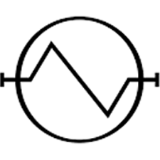
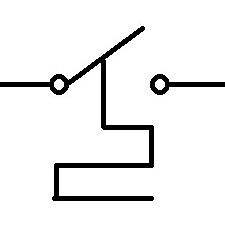
Once you’ve identified the key components, the next step is to understand how they interact with each other. The heat pump schematic diagram uses various symbols and lines to represent these interactions.
| Symbol | Description |
|---|---|
 | Compressor |
| Fan | |
 | Condenser |
 | Evaporator |
 | Thermostat |
| Expansion Valve | |
| Flow Direction |
For example, a solid line typically represents a direct physical connection between components, while a dashed line could represent a control signal or wire. Arrows on the lines indicate the flow of refrigerant or energy.
Understanding the diagram is not just about knowing what each symbol stands for, but also understanding the sequence of events. This can be particularly helpful when diagnosing issues with your heat pump. For example, if your heat pump is not heating properly, you might look at the diagram to see if the problem could be with the compressor or condenser, which are crucial for the heat transfer process.
Interpreting a heat pump schematic diagram can seem daunting at first, but with a bit of practice and knowledge, it can become a valuable tool in understanding your heat pump system. For more complex systems, like a geothermal heat pump, understanding the schematic diagram is crucial. You can further your understanding with our geothermal heat pump diagram.
Components of a Heat Pump
Understanding the basic components of a heat pump is crucial for interpreting a heat pump schematic diagram. The four main components include the compressor, condenser, evaporator, and expansion valve.
Compressor
The compressor serves as the heart of the heat pump system. Its function is to circulate the refrigerant through the system under pressure. This process increases the temperature of the refrigerant, turning it into a high-pressure gas. The compressor’s role is critical in heat absorption and release, which are key aspects of how a heat pump works.
Condenser
The condenser is the component where the refrigerant releases its heat. As the high-pressure gas enters the condenser, it cools and condenses into a liquid. This process releases heat, which is then transferred to the air or water (in case of a geothermal heat pump) that circulates around the condenser coil. You can find more details on how this process works in a geothermal system in our geothermal heat pump diagram article.
Evaporator
The evaporator acts as a heat collector. As the low-pressure liquid refrigerant enters the evaporator, it absorbs heat from its surroundings and evaporates. The refrigerant, now in gas form, carries the absorbed heat to the compressor, where the cycle repeats.
Expansion Valve
The expansion valve plays a crucial role in controlling the amount of refrigerant that enters the evaporator. It also reduces the pressure of the refrigerant, allowing it to expand and cool before it moves into the evaporator.
All these components work in concert, making a heat pump an efficient heating and cooling solution. Understanding these components and their roles is foundational to understanding more complex topics like heat pump wiring or studying a heat pump system diagram. You can also learn more about the cycles of a heat pump in the heat pump cycle diagram article.
How a Heat Pump Works
A heat pump operates in various phases, each vital for its functionality. By understanding these different stages, you can gain more insights into the workings of your heat pump and how to maintain it effectively. Let’s take a closer look at the Heat Absorption Phase, the Heat Rejection Phase, and the Defrost Cycle.
Heat Absorption Phase
In the heat absorption phase, the heat pump extracts heat from the outside environment, even if the air seems cold. This is possible because the heat pump’s evaporator coil absorbs heat energy from the outdoor air and uses it to evaporate the refrigerant inside the coil. The refrigerant transforms from a low-temperature, low-pressure liquid into a high-temperature, low-pressure gas.
The compressor then takes over, increasing the pressure and temperature of the refrigerant gas. This heat absorption process is a critical step in heating your home during cold weather and is clearly outlined in a heat pump schematic diagram.
Heat Rejection Phase
The heat rejection phase, also known as the cooling phase, involves releasing the absorbed heat into the indoor space. The high-temperature, high-pressure refrigerant gas travels to the condenser coil, where the heat is transferred to the indoor air.
As the heat is transferred, the refrigerant cools down and turns back into a low-temperature, high-pressure liquid. This liquid then goes through the expansion valve, reducing its pressure and temperature further, and the cycle repeats.
During this phase, the heat pump operates in reverse, effectively cooling the indoor air during hot weather. The heat pump cycle diagram provides a visual representation of this process.
Defrost Cycle
The defrost cycle is an essential part of the heat pump’s operation during cold weather. When outdoor temperatures drop significantly, frost or ice can build up on the outdoor unit’s evaporator coil. This build-up can hinder the heat pump’s ability to absorb heat from the outside air.
To prevent this, the heat pump periodically goes into the defrost cycle. During this cycle, the heat pump temporarily reverses its operation, acting as an air conditioner to warm up the outdoor unit and melt the frost or ice. The defrost cycle typically lasts for a few minutes and occurs only when necessary.
Understanding these various operational phases can help you better comprehend the complex workings of your heat pump. Interested in more detailed diagrams? Check out our articles on heat pump wiring diagram and heat pump system diagram for a more in-depth understanding.
Common Issues and Troubleshooting
Heat pumps, like any mechanical system, can encounter problems. Understanding the signs of a malfunctioning heat pump and how to troubleshoot using a heat pump schematic diagram can assist homeowners in dealing with these issues effectively.
Recognizing Signs of a Problem
There are several signs which may indicate a problem with your heat pump. Some of the most common ones include:
- Inadequate heating or cooling
- Unusual noises during operation
- Frequent cycling between the ‘on’ and ‘off’ states
- Unusually high energy bills
- Ice buildup on the outdoor unit during winter
These signs might indicate issues such as refrigerant leaks, dirty filters, or problems with the compressor, condenser, evaporator, or expansion valve.
Understanding Common Issues from the Diagram
A heat pump diagram can help homeowners identify and understand the common issues that might be affecting their heat pump. By examining the diagram, you can see how the system’s various components work together and where potential problems might occur.
For instance, if your heat pump is not providing adequate heating, the problem might lie with the compressor or the condenser. The diagram can help you visualize these components and their role in the heating process. Similarly, if your heat pump is making unusual noises, the diagram can help you locate the components that might be responsible, such as the fan motor or the compressor.
Basics of Troubleshooting with a Schematic Diagram
When troubleshooting heat pump issues, a heat pump schematic diagram is a valuable tool. It provides a visual representation of the system and its components, making it easier to identify and diagnose potential problems.
Here are some basic steps for troubleshooting with a schematic diagram:
Identify the Symptom: Determine what exactly is wrong with your heat pump. Is it not heating or cooling properly? Is it making strange noises? These symptoms can guide your troubleshooting process.
Refer to the Diagram: Use the heat pump schematic diagram to locate the components that might be related to the issue you’re experiencing.
Understand the Component’s Function: By understanding what each component does, you can better diagnose the problem. For instance, if your heat pump is not cooling properly, you might want to examine the components involved in the cooling process, such as the evaporator and the expansion valve.
Check for Common Issues: Refer to the common issues associated with the problematic component. For instance, if your heat pump is not heating properly and you suspect the problem lies with the compressor, common issues might include a faulty compressor motor or low refrigerant levels.
Consider Professional Help: If the problem persists or if you’re uncomfortable diagnosing and fixing the issue yourself, it might be best to contact a professional. They can use the schematic diagram to diagnose and fix the issue more effectively.
Remember, while a heat pump schematic diagram can be a helpful tool for understanding your heat pump and diagnosing issues, always consider seeking professional help when dealing with complex system issues or when in doubt.